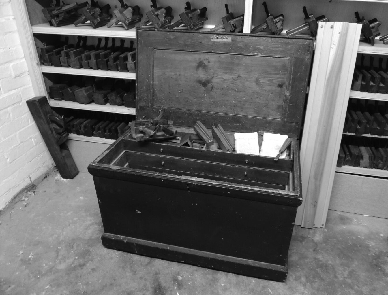
The following is an excerpt from “With All the Precision Possible: Roubo on Furniture.” This book is the result of more than a decade of work by an international team that produced the first English translation of the 18th-century woodworking masterpiece: “l’art du Menuisier” by André-Jacob Roubo. This translation covers Roubo’s writing on woodworking tools, the workshop, joinery and building furniture.
In addition to the translated text and color images from the original, “With All the Precision Possible: Roubo on Furniture” also includes five contemporary essays on Roubo’s writing by craftsmen Christopher Schwarz, Don Williams, Michael Mascelli, Philippe Lafargue and Jonathan Thornton.
The excerpt below details a machine that had gone out general use even before Roubo wrote the original text. However, there is no denying that the illustrations and explanation of the device are captivating. The details on it inspired Jonathan Thornton to recreate one of these machines and write an essay on it for “With All the Precision Possible.” A portion of the essay will be the excerpt for next week.
Description of the Machine commonly called the tool for waves, and the way of making use of
it in different ways
The machine that I am going to describe is the largest and the most complicated of all the cabinetry tools, which once were much used. Now they are not used much, since they are only used for works of applied wood [moldings] and they have, so to speak, combined all their science to veneer the wood properly. However, since this tool is ingenious, and you cannot find it anywhere, I thought I must include it here, in order to save it for posterity, supposing that this work succeeds.3
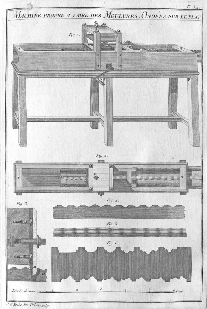
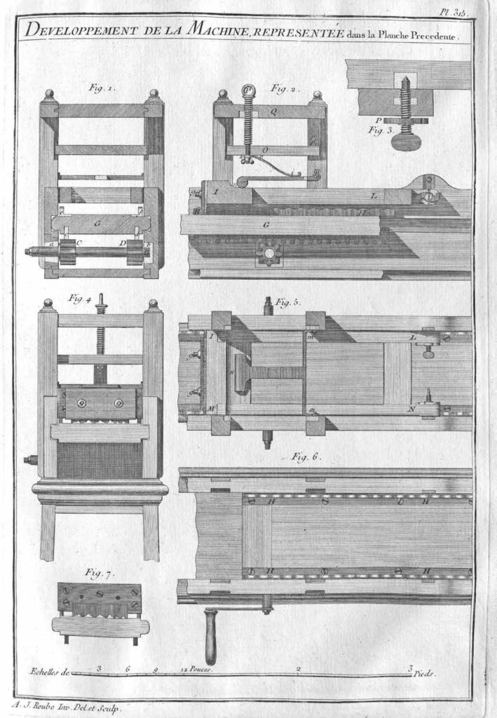
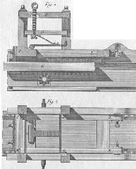
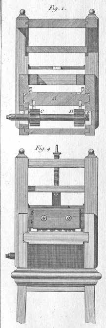
The use of the wave-cutting Tool represented in Fig. 1 is for cutting onto the wood wave-mouldings, or patterns, precise intricate repetitive designs, whether flat, on the face or even in both directions at the same time.
It is composed of a box from 7 to 8 feet in length, by one foot wide and 9 to 10 thumbs in height, exterior outside measurements. This box is open on top and at the ends, such that the distance between the two sides is retained only by cross-pieces A and B, Figs. 1 & 2, placed at two ends of the box, where they are assembled by mortise and tenon. At about the middle of the height of the box is placed a plank C–D, Fig. 2, about 2–thumbs thick, called a sommier [or platform, mattress; in similar machines for printing lithographs this is called the couch or the cooch]. This, for more strength, should be fit together at the ends and braced from below. This plank, or sommier [platform], is held in a groove in the two sides of the box (which should not be less than one–and-a-half thumb in thickness) and serves to hold the mouldings to be wave-cut, as I will explain later, and which you can see in Fig. 2, which represents the machine viewed from above.
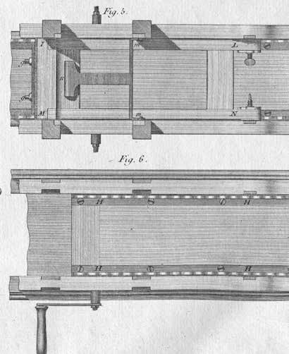
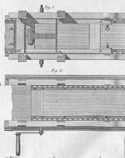
In the middle of the box is placed a square frame of about a foot in width, viewed from the side, and which extends from 9 to 10 thumbs above the box, to the sides of which it is attached with some screws, and in which it enters by tenon and a notch, as you can see in the evolution of this machine, represented in the following Plate [315] Figs. 5 & 6.
The width of this frame is determined by the width of the box, the sides of which the uprights of the latter are flush on the interior. It is in this frame that is placed a spring which presses on the toolholder [the cutterhead] E, Fig. 1. This spring is raised and lowered by means of the screw F, Figs. 1 & 2.
The whole machine is held on a base of a solid construction and widened [splayed] in the form of a trestle to give it a better footing. The height of this base should be from 2 feet 8 to 10 thumbs, so that is has about 3 feet in height from the axis of the crank handle G to the ground. This is the most comfortable height for the person who turns this crank handle to have all his strength, whether raising or lowering it.
There are in this machine two movements: one is horizontal, which is done by means of the handle G, Fig. 1, which by making the pinion turn placed in the interior of the box, moves the sommier A–B, Fig. 2, and consequently the work which is held above.
The other movement is vertical, downwards, and depends on the first. The rod, or wave guide/ channel H–H, Figs. 1 & 2 [Plate 315], which is held on the sommier, moves therefore with the latter, is raising the tool-holder F, Fig. 1, left, which then lowers immediately by itself, both by its own weight and by the pressure of the spring placed above. See Fig. 4, which represents a wave channel the size of the execution [ full-size/scale] Fig. 5, [which] represents a moulding completely wave-formed, according to the sinuosity of the wave channel in Fig. 4. Also see Fig. 3, which represents the cross-section of the tool-holder, which I will describe here later.
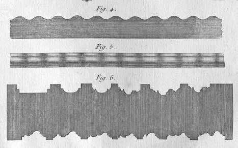
Fig. 6 represents a cutting blade viewed with different profiles, as large as the execution [ full-size/scale].
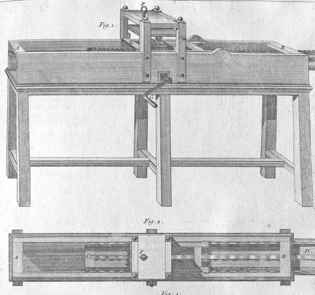
Figures 1 & 2 of this plate represent one of the transverse cross-sections of the machine, taken at the location of the pinions and the other the longitudinal cross-section of the same machine, so as to better understand the details of its construction and the mechanism of its operations.
Axis A–B, should be placed in the copper collars, a, b, so that they turn more easily. One should note at one of the sides of the box [is] a squared opening capable of letting pass pinions C–D, supposing that it is necessary to remove the axis outside. Pinions C–D, engaged in the toothed rack c, d, Fig. 1, and E, F, Fig. 2, which are embedded on the underside of the carriage [platform] G–G, same Figure, about 9–lines deep, and are held there by pegs, placed together in the sides of the latter, observing that the toothed racks are well positioned vis-a-vis the other, so that the two pinions C–D, Fig. 1, are contacted equally by the racks [platform] above. However, as it can happen that the teeth of the pinions are not well positioned vis-a-vis the other, one would do well, after having stopped/blocked one of the toothed racks, not to attach [secure] the other until after verifying that it fits well with its pinions, so as to be able to set it back or advance it as necessary.
These racks can be made of iron or copper, which makes no difference for the machine, however it would be good that they be made of copper, given that the rubbing of two different metals is smoother and wears less than if the two pieces, that is to say, the rack and pinions, be of the same metal. [See Plate 314.]
The rods or wave conduits [channels or guide rails for the work piece] e, f, Fig. 1, and H, H, Figs. 2 & 6, should be also made of copper, and they should be bent at a right angle to have the ability of attaching them with screws on the carriage [platform] in which they are notched in all their thickness, as one can see in Figs. 1 & 6.
When you put these [wave] channels on the platform, you must pay the greatest attention that the guilloche [pattern] be not only fit well together, but also that they match at the same point of their contour with the contact of the tool-stand which bears on top of it, as you can see in Fig. 4. This represents the machine viewed from the end, and even better in Fig. 7, which shows the toolstand [tracing and cutting head] where you have removed the cheek [ fence] which holds the iron in place, as I will explain later.
The tool-stand is a frame I–L, M–N, Figs. 2 & 5, of about 2 feet in length, by a width equal to the interior of the box, less the necessary play to prevent any rubbing, which you avoid by diminishing the thickness of the uprights in the entire length, and reserving there some heels at the ends, so that the frame is held against the sides of the box, and cannot get out of place when you move it.
The frame of the tool-stand is attached at the sides of the box by means of two threaded bolts, represented in Fig. 3, half as large as executed here, where the extremity o ends in a cone, and bears on a copper collar embedded in the side of the box.
This screw is held in place in the frame by a nut placed in the middle of its thickness, normally. To prevent the movement of the frame so that it does not turn the screw, you put a counter-screw P outside, which you tighten against the frame, which prevents the screw from making any movement. See Figs. 3 & 5.
As it is sometimes found where it is necessary to lift the point of the movement of the toolstand, you pierce many holes in the copper collar attached to the side of the box, as I did in Fig. 2.
At the other end of the tool-stand, that is to say, where the cutting iron is secured/fitted, the cross-piece I, Fig. 2, should be very strong and assembled with a cover from above so as to present a uniform surface all along the length, which is the width of the tool-stand. Then you apply from above a piece of iron attached with some screws with countersunk heads, of a length equal to the width of the latter. And you make it overlap by about 5 or 6 lines at both ends, to make two frets that bear on the wave pattern [channels], and you make a notch in the middle of this piece of the size of the iron for positioning the cutting iron of the tool, as you can see in Fig. 7.
This iron is held in place by a cheek [ fence] (whether of iron or copper, either is equal), that you hold in place by means of two square-headed screws, g–g, Figs. 2, 4 & 5, where the nut is placed in the thickness of the cross-piece of the frame. See Fig. 3 of Plate 314, where I showed the cross-section of the tool-stand, with the contact I, the iron L, and the exterior cheek [ fence] M, which comes down as low as possible, that is to say, just to the bottom of the part the most hollowed of the latter.
The bottom of contact I [Plate 314] should be the thinnest possible (without however being a sharp edge), so that it follows well all the contours of the wavy pattern N–O. You must take great care that the point of contact for the fret be in the same direction as the iron cutting edge [both bevels are in the same direction], as I noted in this figure, so that the movement of the tool (which is made in describing an arc, where the center is found at the end of the frame) be less noticeable. I have partially remedied this by lengthening the point of the center of movement as much as has been possible.
The weight of the tool-stand should be almost sufficient to make the cutting iron bite into the surface of the wood workpiece. However, one must always put a spring there, both for augmenting the weight of the tool, supposing that it be necessary, and preventing it [ from] jumping around.
This spring h–i, Fig. 2, does not bear immediately on the tool-stand, but on a lever where its arms are loosely attached to the uprights of the movable frame of the box at m, Figs. 2 & 5.
The other end bears on the cross-piece of the tool-stand at n, which augments at the same time the strength and the elasticity of the spring, where the upper part is held below the small shelf O, Fig. 2, with screw P, where the nut is placed in the top of the frame Q. This screw serves, as I already said, to increase or diminish the pressure of the spring. The small shelf O through which passes the lower end of the screw, serves nothing but to hold it in place, and to press the heel o of the spring. As this small shelf is movable, you hold it from the opposite side of the screw with two pins, which you place across the uprights of the frame, as indicated by points p–p.
I made the head of the screw P in the form of a screw-eye, so that one cannot tighten it or loosen it by simply touching it, and so that you have need for a little pry bar or crank handle to do it. Those who approach the machine while it is adjusted cannot disturb anything there by simply touching it.
It is for this same reason that I prefer the screws with squared heads for closing the cheek [ fence] of the tool-stand, because a wrench is necessary to move these sorts of screws. You can eliminate their access from everyone’s hands, and consequently prevent anyone from changing anything on the tool.
As to the manner of using this machine, it is very simple. You begin by planing some wooden strips to the thickness of the profile that you have chosen, and the projection of the waves. This being done, you put in the tool-stand a smooth iron, which you adjust to the height equal to the projection of the moulding. You hold the strip on the platform, by means of little iron points placed [on the latter by equal distances from each other], and you make the machine move by turning the crank handle, which advances the platform forward. Consequently, the strip that is attached to the platform, after having passed many times under the smooth iron, is found to be wavy on its surface.
When the strip is thus finished, you remove the smooth iron, and you substitute the one that is shaped with a profile, and you begin the operation again, just until the iron is not cutting the wood any more, and consequently the moulding is perfectly finished.
You must take great care before running the moulding to verify that the wooden strip is placed truly parallel, which you know by making it pass the entire length under the blade that you hold elevated above. You should secure the strip on the platform only after having taken this precaution. You must also note that the pins that you place in the platform to hold the mouldings are positioned in the middle of their width [thickness of the moulding stock], and that they do not project enough to be able to meet the blade and cause any breakage, which you must take great care to avoid.
The blade of the waving tool is always placed perpendicular to the workpiece, which makes it scrape enough to cut, which cannot be otherwise, given that if you slant it in the normal way with moulding planes, it would scratch/drag on the wood as it comes against the grain, which happens at each undulation. What’s more, the blade thus slanted will no more be found in the same direction in all parts, which you must avoid as much as possible.
Since you can make many different blades, you must pay attention that they be all the same width, so that they completely fill the notch made in the piece which makes the cuts. You must also pay attention that they are all the same thickness, and that this thickness be considerable, to better resist the force of the wood in passing below.
The handle with which you move the waving tool can be placed to the right of the machine, as in Fig. 6, or to the left, as in Figs. 1 & 4, which makes no difference.
Each of these ways placing the handle has its advantages and disadvantages. If you place it to the right, which is the most natural way (since you made some effort pushing it), you cannot see the work well, behind which you position yourself. If on the contrary you place it to the left, you see the work clearly, but you are required to turn the handle in reverse. That is why, in order to eliminate these two inconveniences, I believe it would be better to position the two ends of the axis so that each one can receive a handle, like in Fig. 5, such that you can use it as you judge appropriate, whether on the right or on the left, or even from both sides at the same time.
3 It has not been possible to find a surviving wave-cutting Tool to make a good description of it. I have had only two iron blades, sold with other scrap metal which have nevertheless been very useful for fixing certain sizes, that I could not have known except for the description that Mr. Felibien made of this tool, which is otherwise very succinct, but imprecise, such that it could serve only to give me an idea of this machine, which I have then arranged in such a manner that it appeared to me the most likely. It has been greatly wished that those who have described this Machine in the Encyclopedia [of Diderot] had done something other than copy Mr. Felibien, instead of adding to the obscurity and inexactitude, as they have done. It would have been very useful to the public, and in particular to cabinetmakers, for whom they would have saved, or better said, presented one of their principal tools.